Modding the $35 Redragon K552 TKL (80%) keyboard
Saturday, December 18, 2021
Click here to go to all posts.
With several modifications, you can turn the Redragon K552 TKL (80%) into a pretty solid keyboard
Table of contents
- Introduction
- Starting point
- The mods
- Parts and prerequisites
- Detachable USB cable modification
- Design modifications
- Finished board and sound test
- Thoughts and future modifications
Introduction
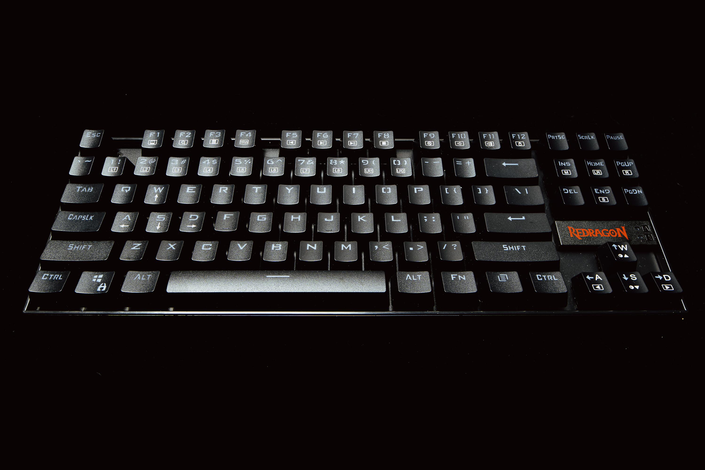
The Redragon K552 is an extremely popular, medium-low cost mechanical keyboard. It comes in a few variations with different mechanical switches and LED configurations.
“Modding” a mechanical keyboard means a variety of things in the keyboard community. In the context of this post, I’m primarily talking about design modifications that don’t change the features of the keyboard. There’s one exception to that, which you’ll note later.
There are likely other—perhaps better—ways to categorize the keyboard experience, but let’s work with this for now!
I decided to start with this medium-low cost keyboard and to try to improve it based on mods I’ve performed on other keyboards, as well as one that I’ve never done before. Note: I’m describing this as medium-low cost as there are certainly less expensive keyboards (e.g., $10) and way more expensive keyboards ($200-2000+).
Starting point
I chose to purchase the linear switch (Red) version of this keyboard with RGB LED lighting. You can find it via this (non-affiliate) Amazon Smile link. Generally, this keyboard goes for about $35. Previously, it has dropped to $20 during sales and I encourage you to check second-hand sites like eBay, as it seems to go for as low as $10-15.
Out of this box, this keyboard has a couple really noticable issues:
- It has an attached USB cable. Design aside, this means that you can’t pick a cable of the ideal length for your setup and, should something happen to the cable, makes it so you cannot replace it easily.
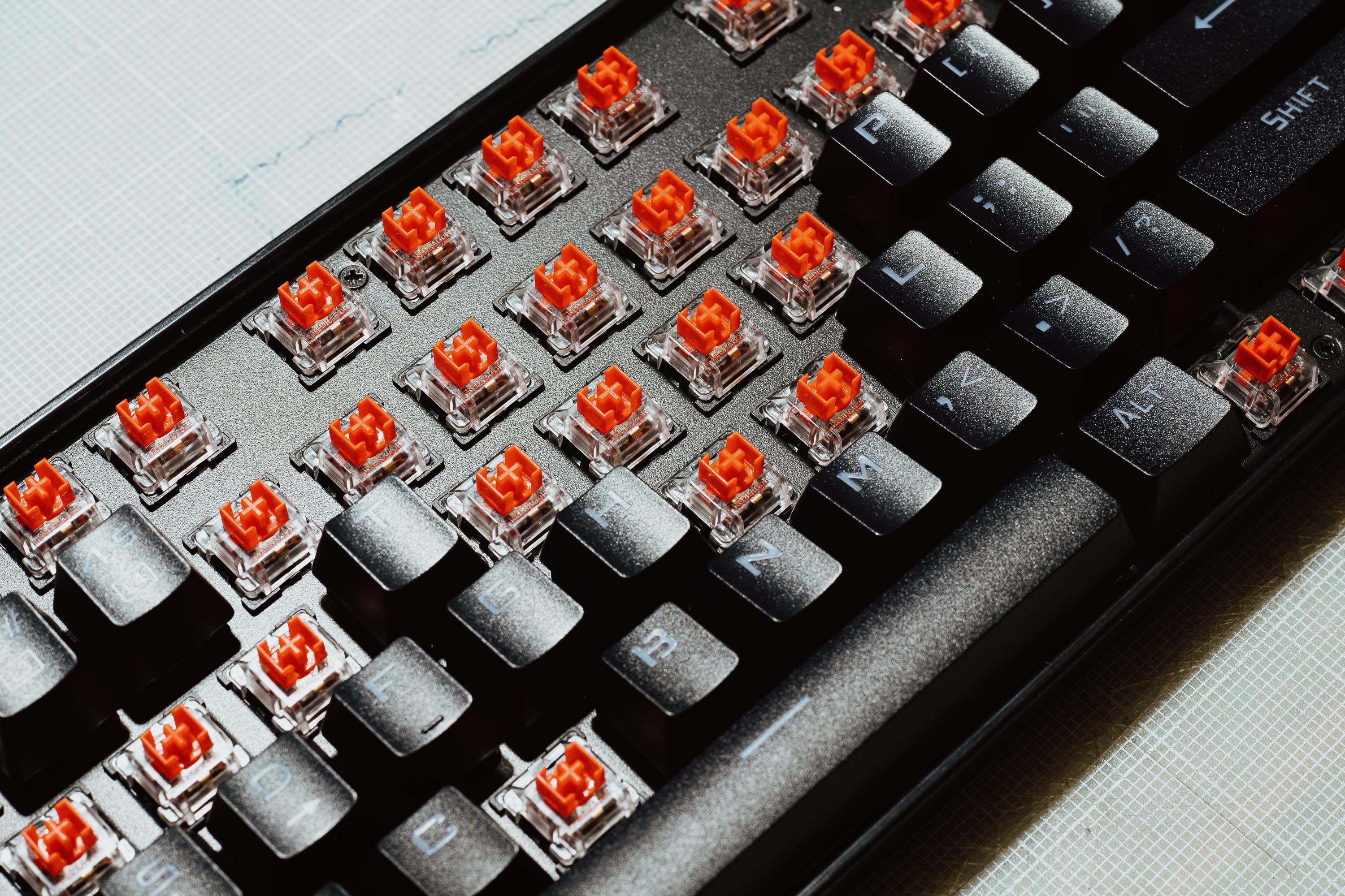
- It doesn’t sound great. This keyboard uses Outemu Red switches.
The good points about this keyboard:
- It uses standard plate-mount stabilizers. Other, more expensive keyboards that I’ve modded, such as the Das Keyboard, use Costar stabilizers, which is less ideal.
- It is pretty easy to open, as it uses only Phillips-head screws.
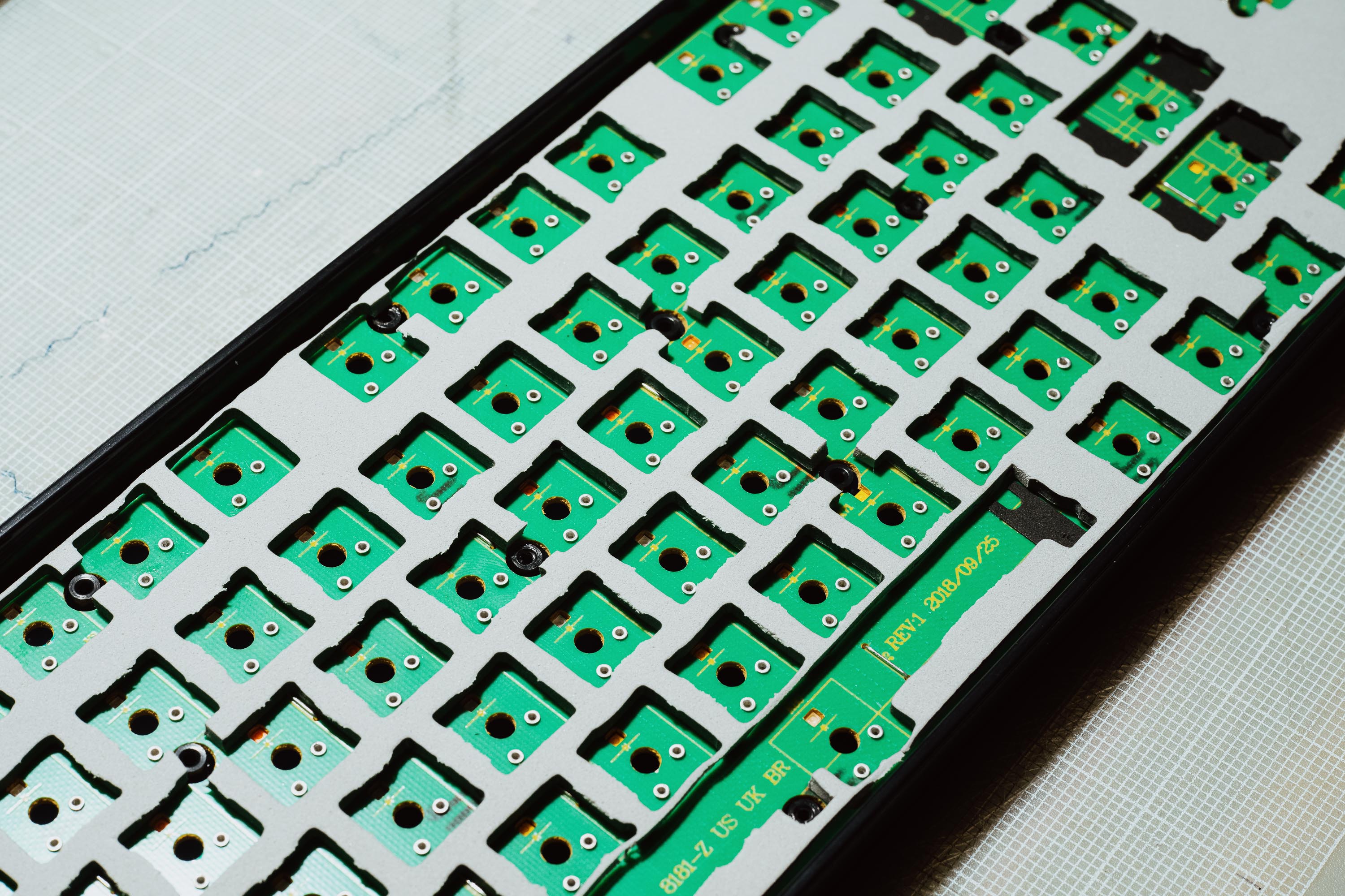
- It has a metal switch plate, which, while not particularly amazing, is better than lower-quality plastic one.
The mixed points about this keyboard:
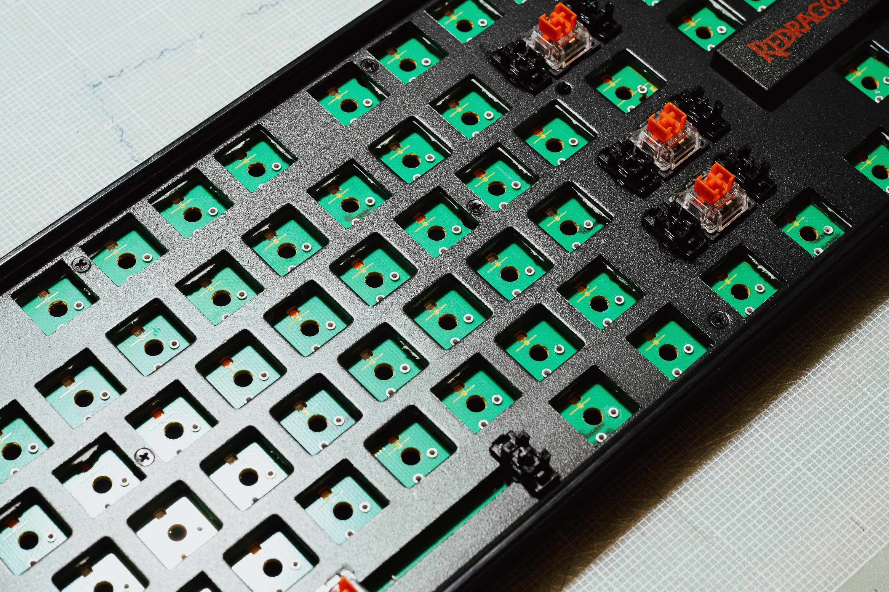
- The switches are sort of hotswap. Specifically, it uses tight sockets soldered to the PCB that only work with Outemu switches, as their metal legs are thinner than other MX-style switches.
The mods
Most importantly, I wanted to address the lack of removable USB cable functionality. More on that later!
I also chose to do many common design modifications:
- Add silicon to the bottom case to create a heavier feel and dampen the sound.
- Lubricate and modify the stabilizers to create a smoother feel and quieter sound.
- Place pads on the PCB to dampen the sound of the stabilizers.
- Remove the switches and
- lubricate the springs to eliminate the high-pitch ping sound, and
- lubricate the stem and bottom housing to create a smoother feel and quieter sound.
- Create and add custom EVA foam between the PCB and the switch plate to dampen the sound.
Parts and prerequisites
To do the design modification, you will need:
- Something with which to cut EVA foam. Examples:
- Common but time-consuming: a sharp knife, like a hobby knife
- Less common but faster (what I used): a laser engraver
- Untested: an automated cutting machine, but machines like a Cricut may not work with foam of 3mm thickness
- Silicon mold making kit: Amazon - ~$9 (only used ~30% of the kit)
- Something to mix the silicon in. I used a plastic takeout container and a wood mixing stick
- 3mm EVA foam: Amazon - ~$3 (only used about ~25% of this roll)
- Lubricant for the stabilizers. I used Krytox 205g0 (various sellers) and Permatex grease Amazon - ~$3 (estimated based on the amount I used)
- Lubricant for the switches. I used Krytox 205g0 (various sellers) - ~$2 (estimated based on the amount I used)
- Pads or cut-up bandages to place where the stabilizers may hit the PCB. I used pads from KBDfans - ~$1
To do the detachable USB cable modification, you will need:
- Access to a 3D printer
- Soldering iron, solder, and basic soldering skills
- 1x 3D printed part: Download files - ~$2 (in material cost)
- 2x M2.5 4mm screws: Amazon - ~$0.05
- 1x Micro USB receptacle: Amazon - ~$0.85
- Note: you can do USB-C as well, but that’s up to you!
- 1x Detachable cable (any) - likely $0
Parts total cost: ~$21
Digital files
Here are the digital files for these modifications parts:
- STL to print: .stl file
- Backup download of the STL on Thingiverse
- Blender project if you want to directly modify this in Blender: .blend file
If you plan on using a laser engraver to cut the EVA foam, here is a Lightburn file: Lightburn file. Note: Remember to adjust the power/speed settings for your machine. There are two problems with this file: it doesn’t have fully straight lines since it was done from a hand tracing and it’s missing some standoffs that you will have to cut out by hand. I may fix this in the future.
Detachable USB cable modification
For cost and familiarity purposes, I chose to go with a Micro USB receptacle, rather than the more modern USB-C. For a future keyboard, I’ll likely try USB-C instead. Feel free to try as well!
On the K552, the attached USB cable is held in plate with two points:
- A molded plastic piece on the case to hold the cable to the case
- A connector to plug into the receptacle on the keyboard PCB
I wanted a pretty clean look to the keyboard, so I decided to try my hand at using Blender to model a new piece for the case from scratch.
Fortunately, a set of digital calipers came in handy here! I chose to do the time-tested method of sketching this out on paper as I was going, which I highly recommend.
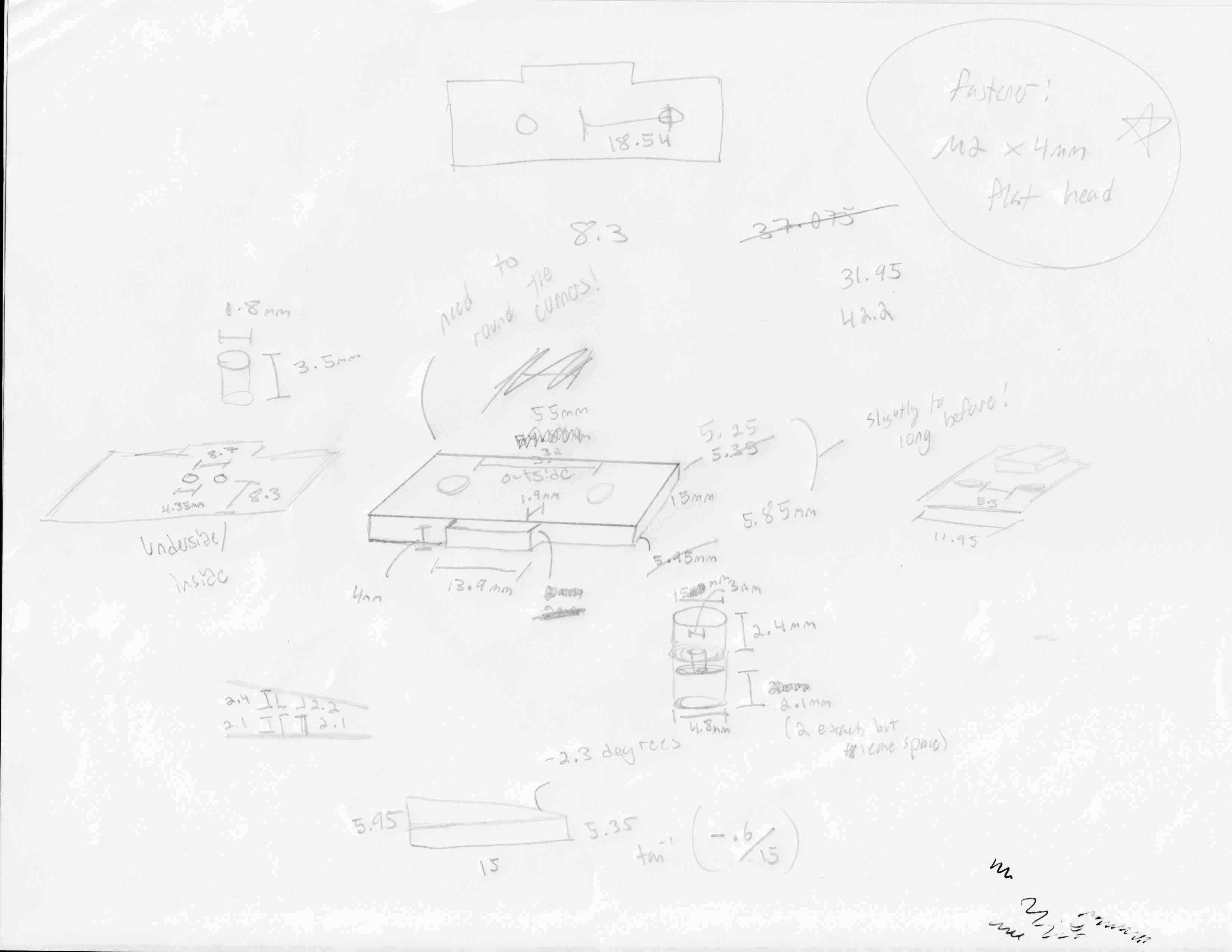
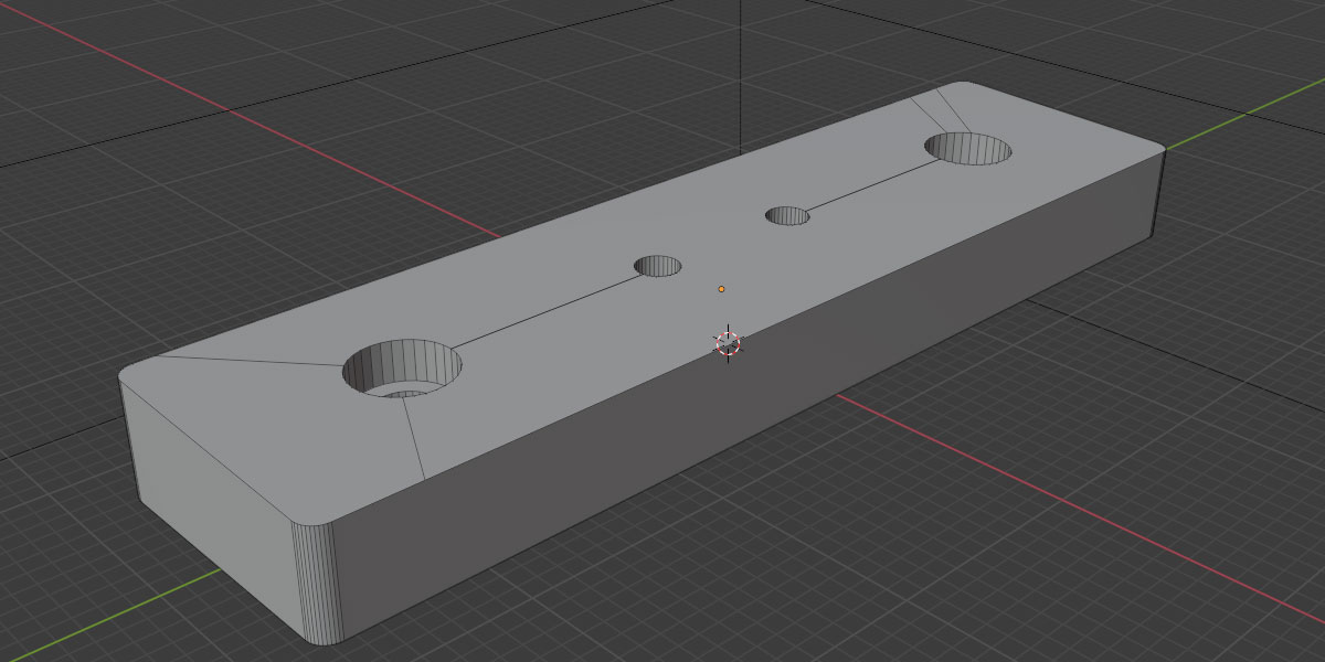
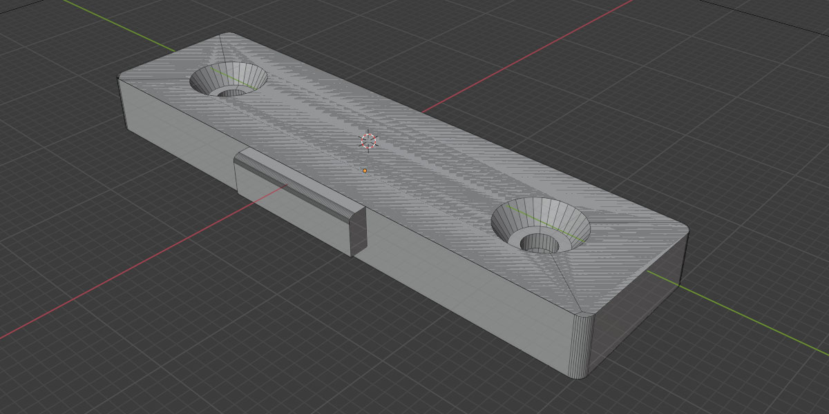
From there, I modeled the part in Blender. This is my second time doing precision modeling in Blender, so it was a fun learning experience and a mostly straightforward part to begin with. A more advanced modeler could probably create a version that uses less material and prints faster while retaining sufficient structural integrity, but I’m content with where I landed.
I printed a couple initial versions to gauge corner rounding, part height, and screw hole dimensions. By the third print, I felt it was sufficiently accurate to proceed. Here are the prints side-by-side, along with the original part.
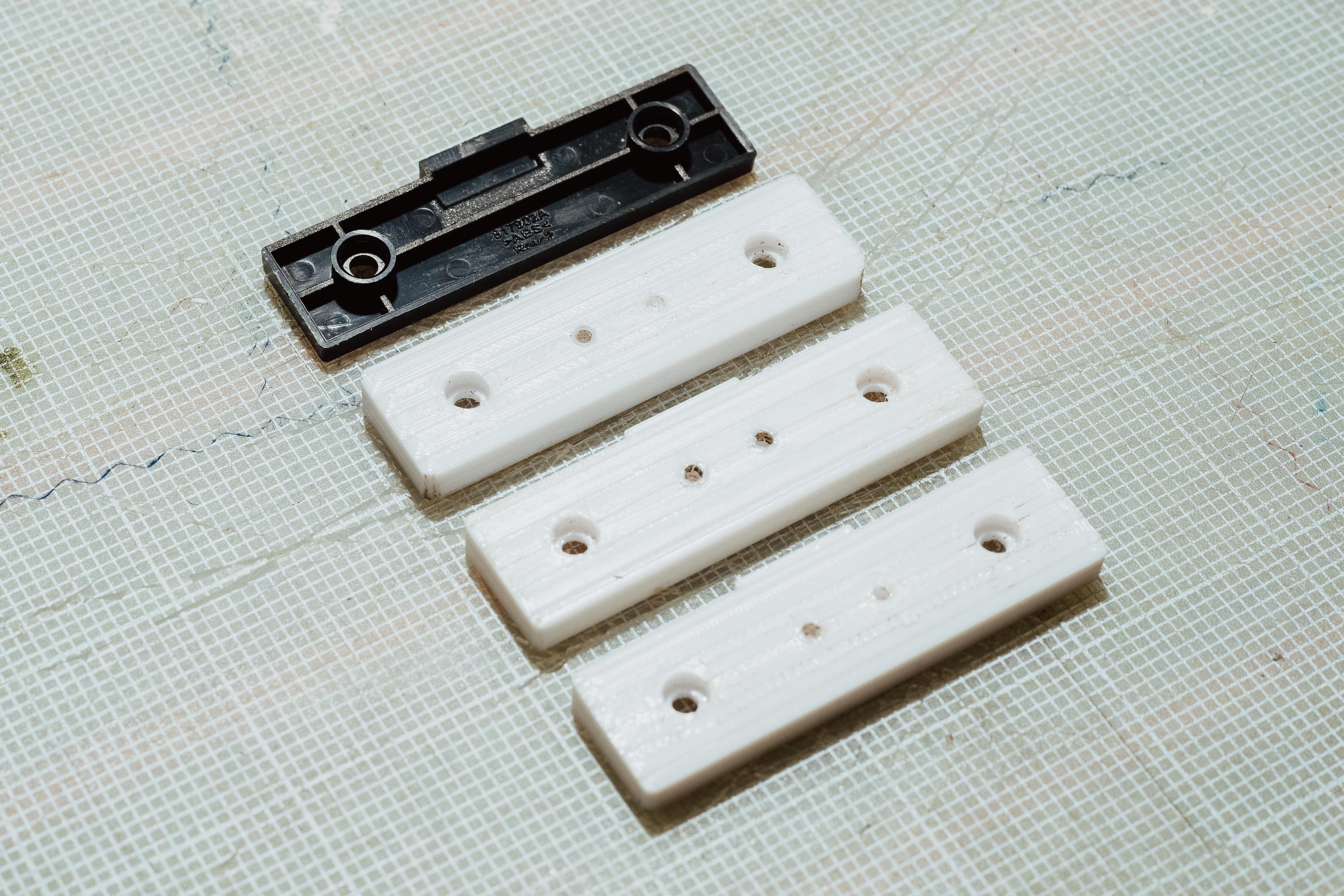
Check the Digital files section earlier to download the STL and Blender project for this part.
3D print settings I used:
- Material: PETG
- Line height: 0.16mm
- Infill: 20%
- Supports: Yes
- Raft: up to you
- Orientation of the part: I recommend orienting the part so the angled screw wells face down. This makes it easier to remove the tiny supports.
You can likely use most common materials, such as PLA, PETG, and ABS. I have only printed this with PETG.
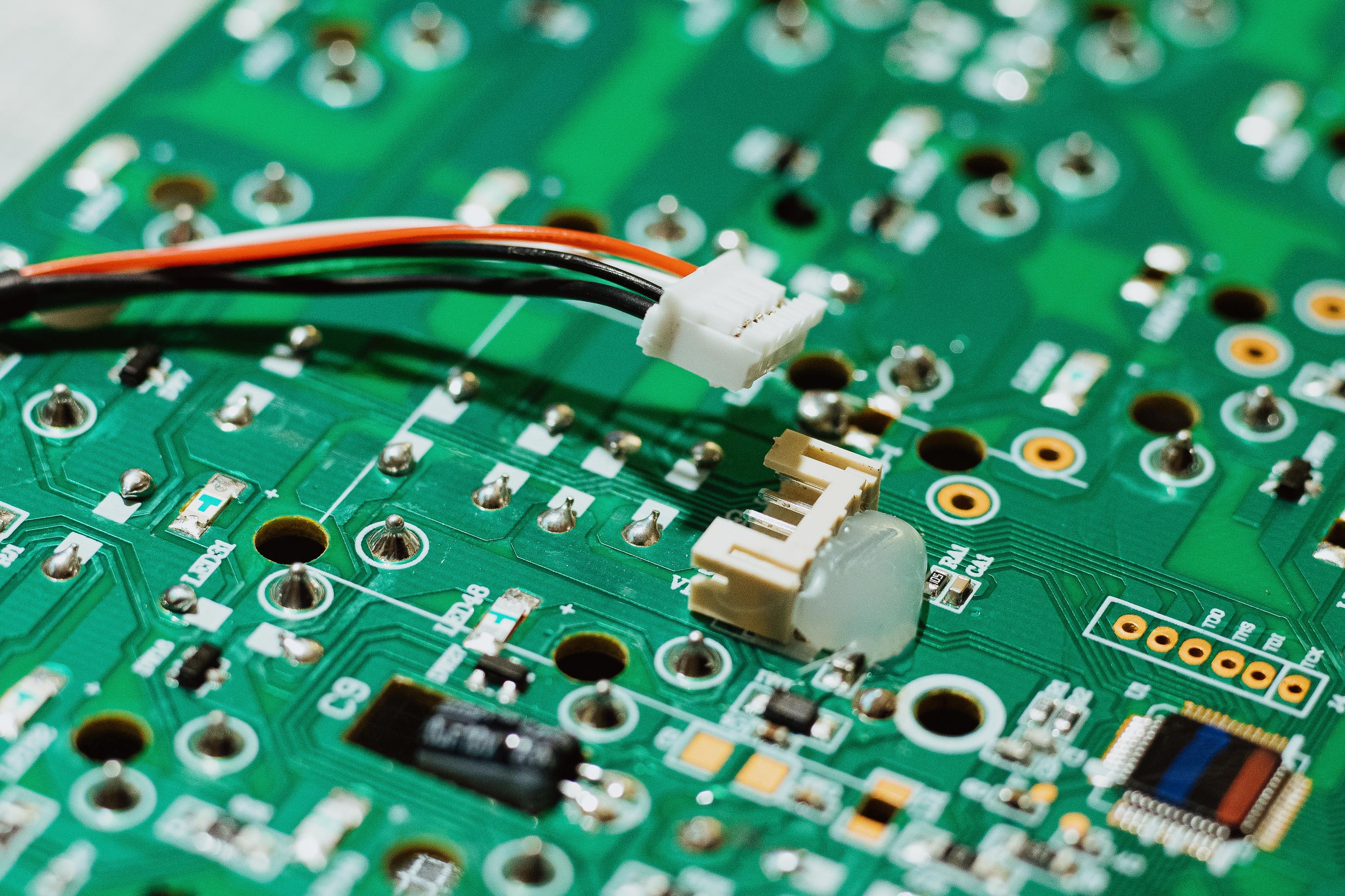
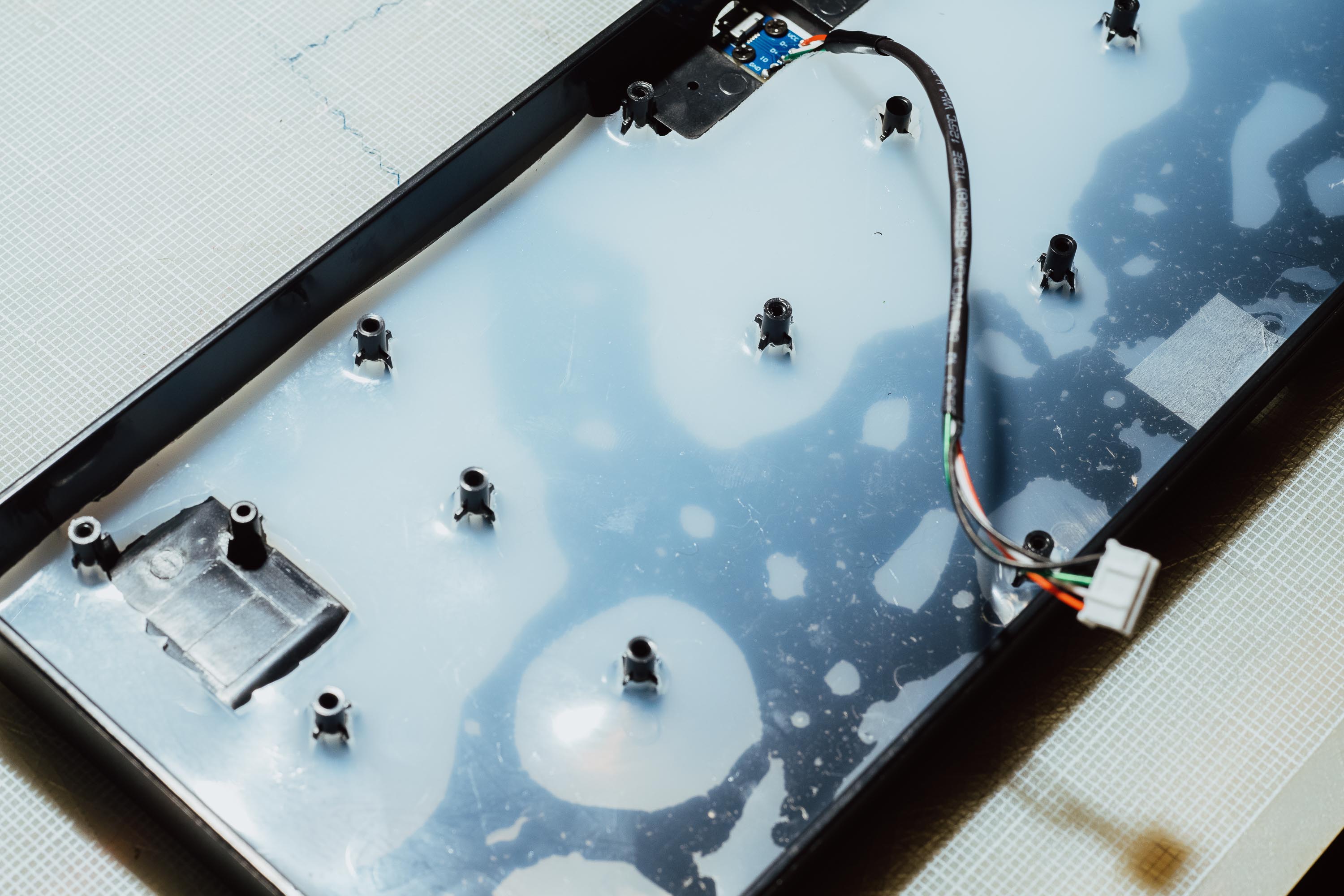
Once you have 3D printed the part, you’re ready to go. To perform this modification, you’ll need to disassemble the keyboard and detach the cable from the PCB, like this:
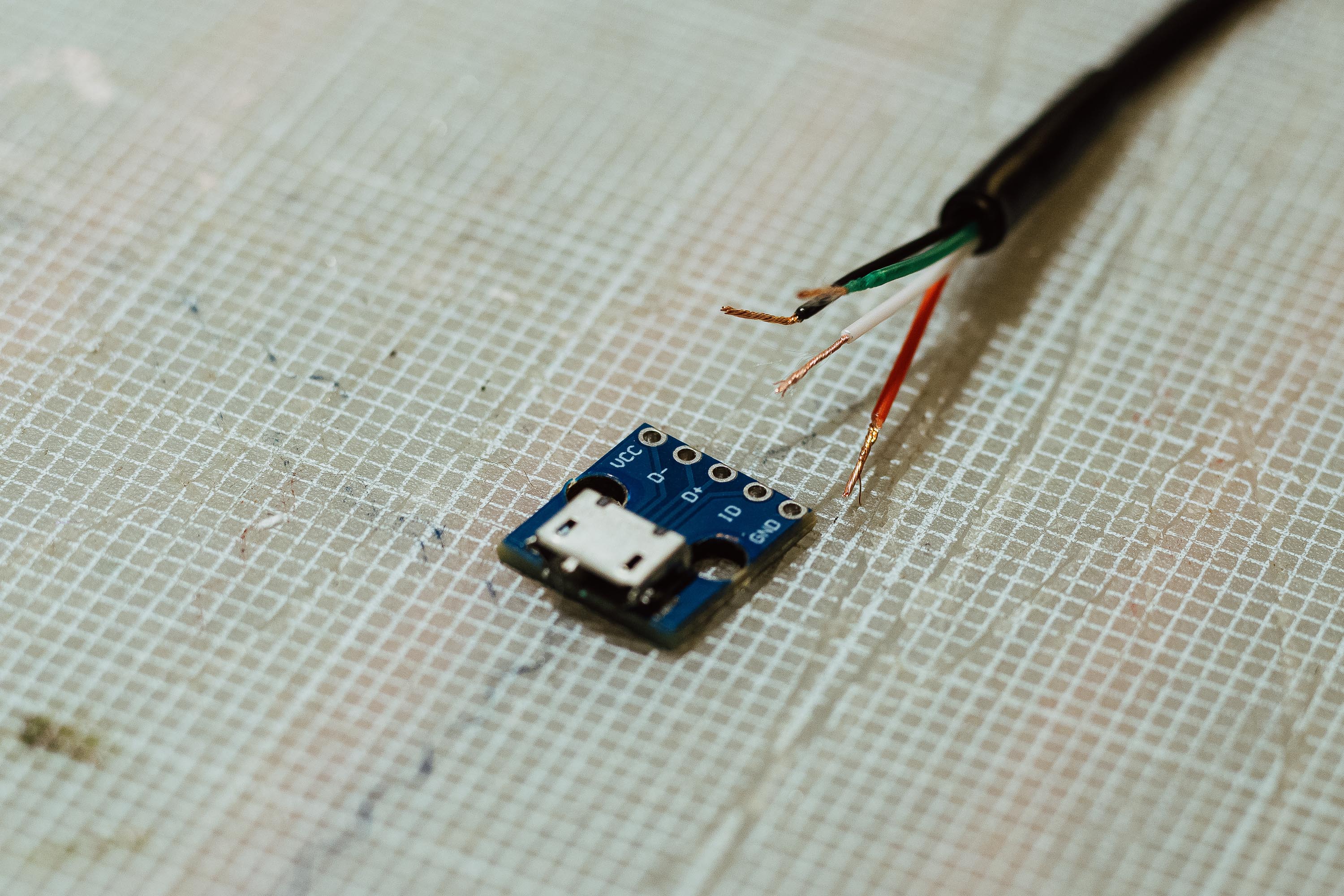
Next, you’ll need to cut the USB cable at a good spot. I chose to cut it near where the cable was previously held by the case.
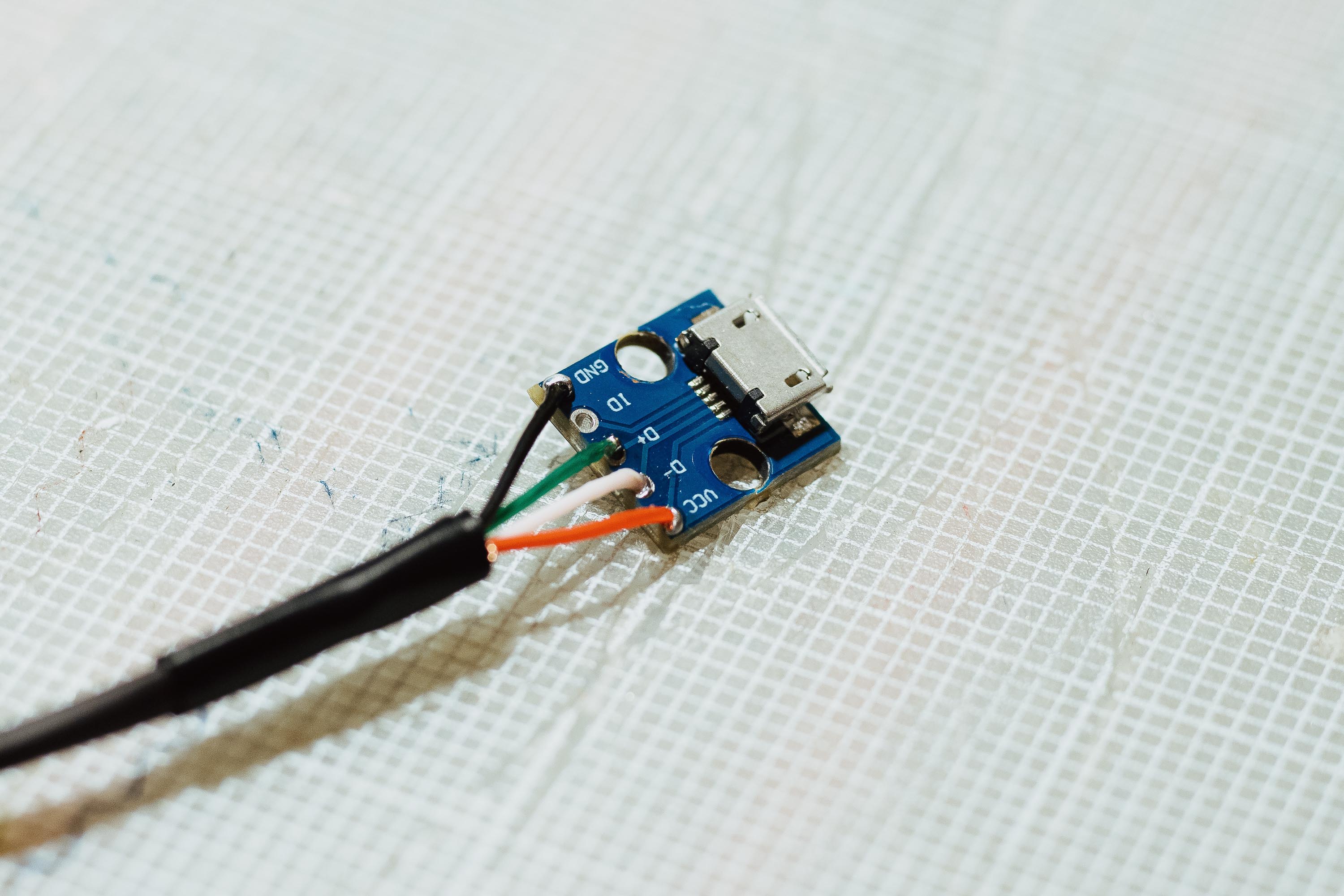
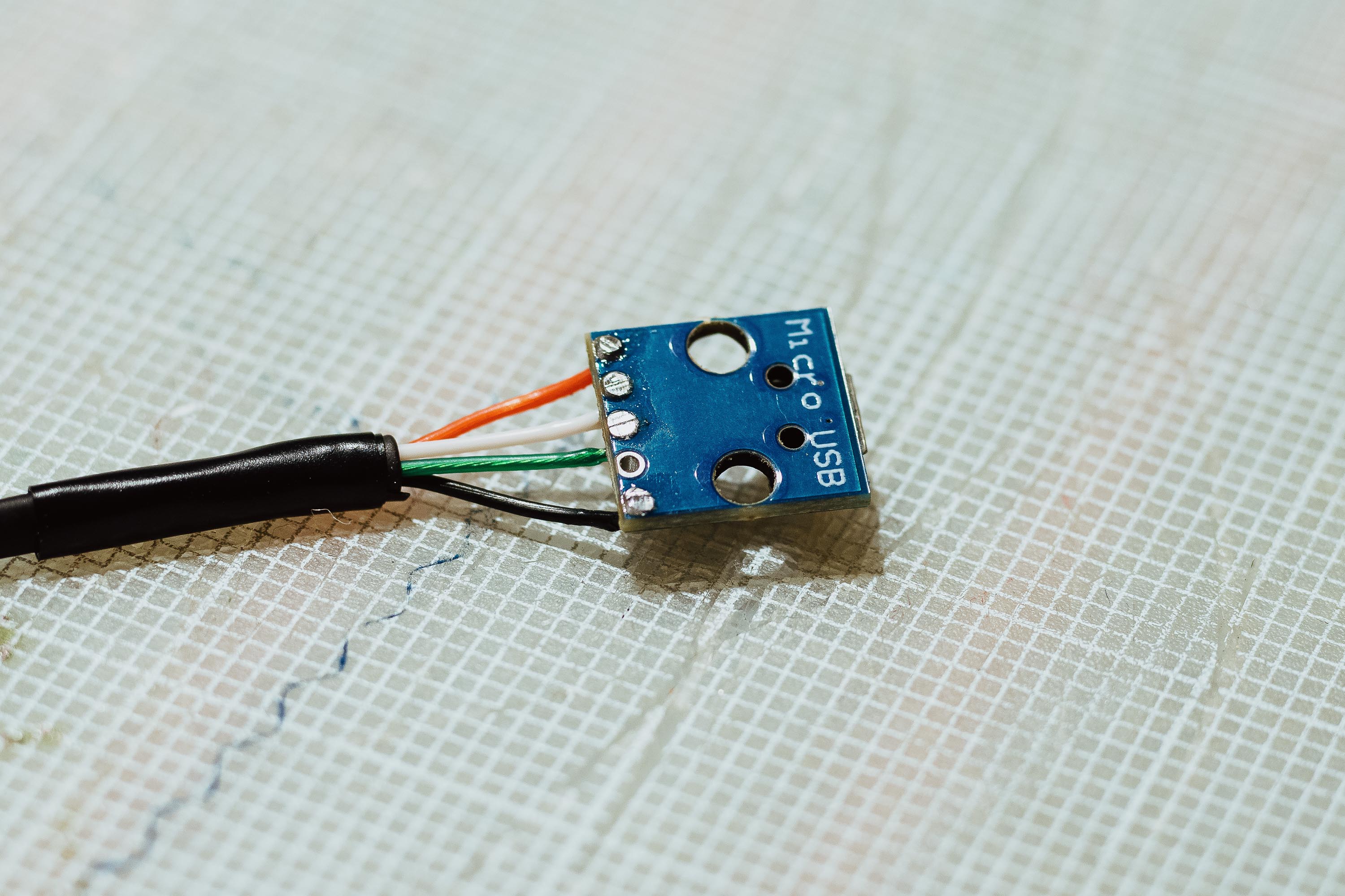
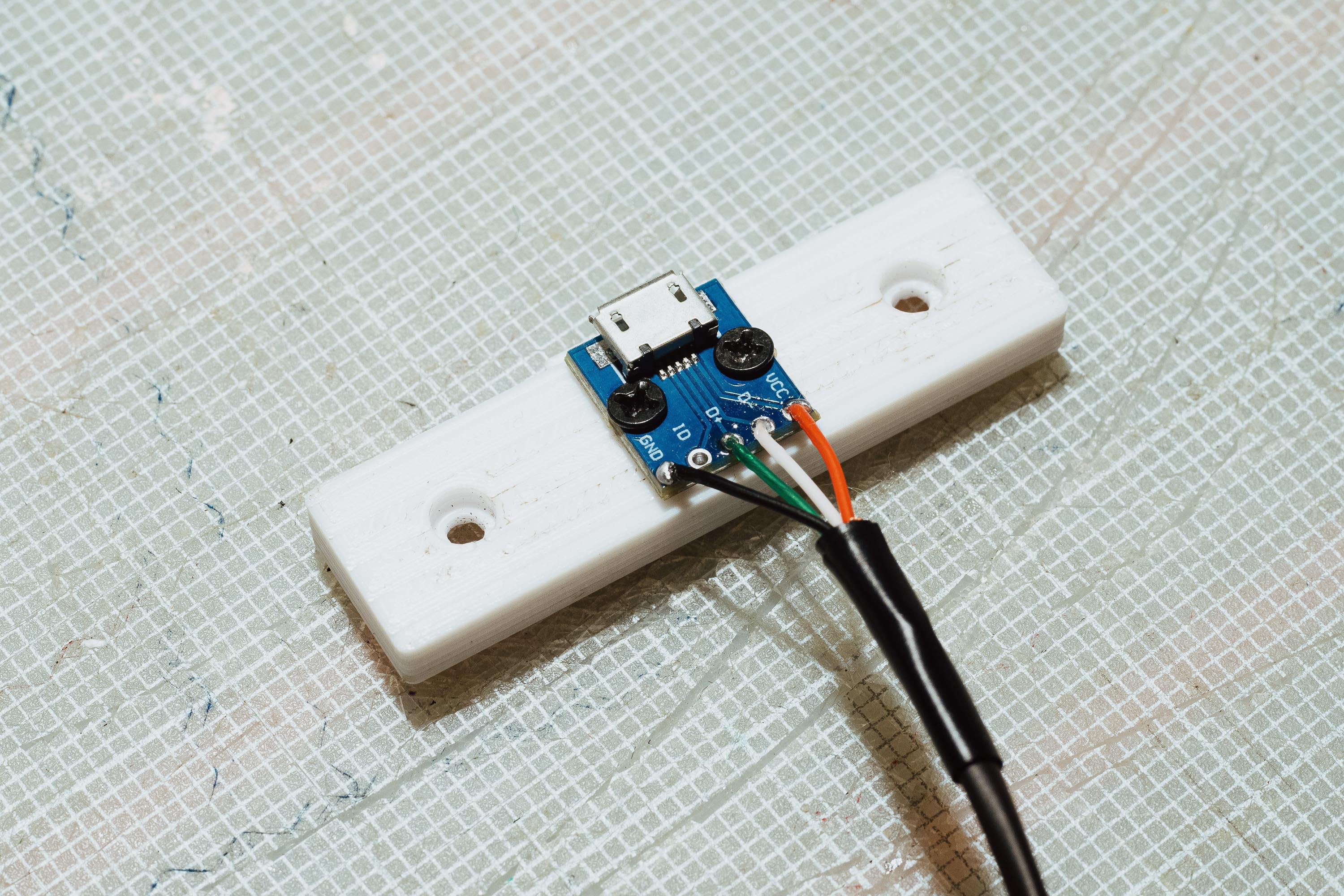
Once you strip the individual wires, they can be soldered to the receptacle. Here are some photos of that.
From there, you’ll mount the receptacle to the printed part with the M2.5 4mm screws. I chose these as the right balance of length, width, and head size. Here’s what this looks like when mounted.
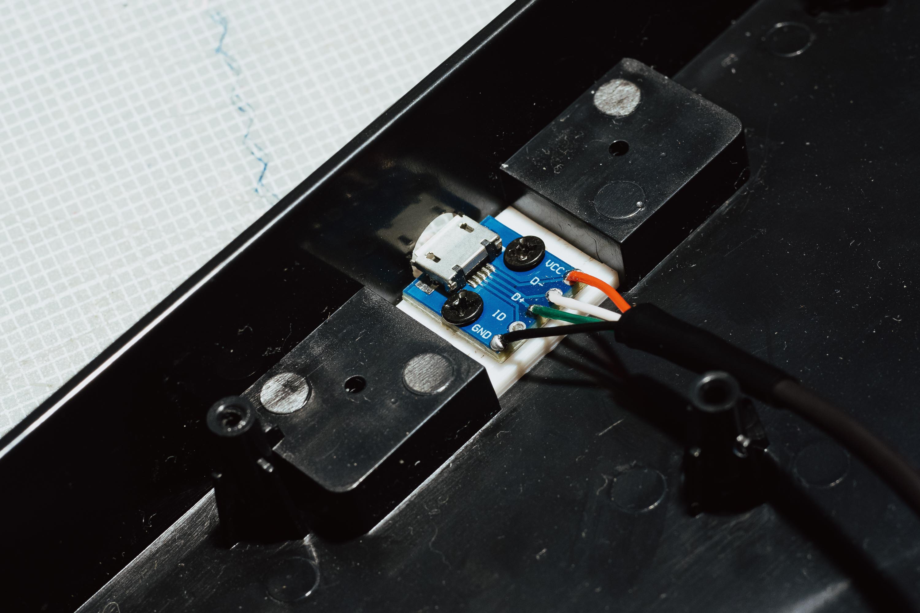
You should now do a test fit on the keyboard to make sure that the part fits and the USB cable can successfully plug into the receptacle. You may need to slightly adjust the receptacle, given that there’s room around the screws.
At this point, you can optionally choose to do the design modifications!
Design modifications
I didn’t take photos of all the modifications, but here are a few.
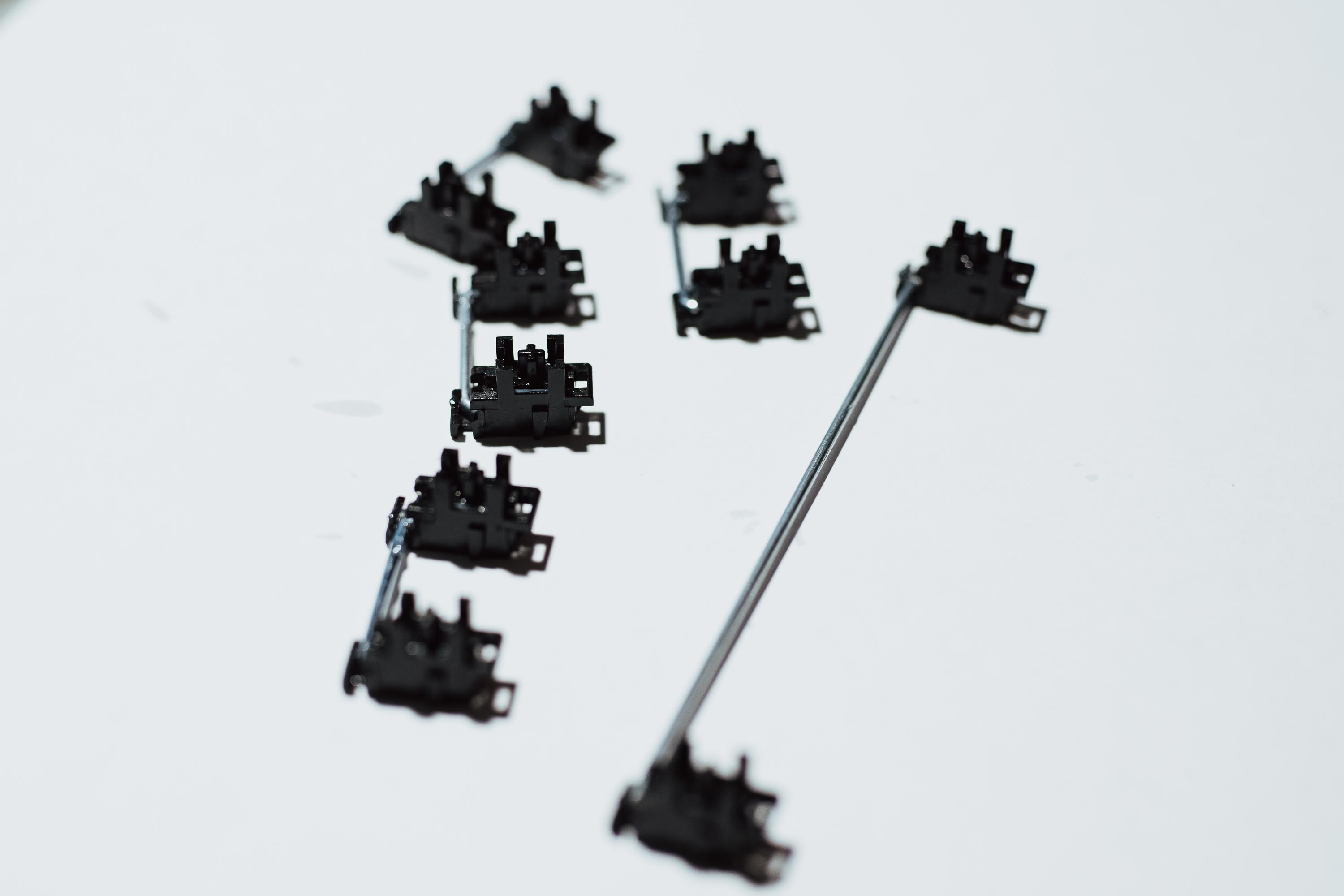
I took out all of the Outemu switches and lubricated the springs and stems. There are enough videos and guides for this online already! Some videos:
- Guide to stabilizer tuning: https://youtu.be/usNx1_d0HbQ
- Guide to bandaid modding (starts at 309 seconds): https://youtu.be/cD5Zj-ZgMLA?t=309
- Silicone mod example tutorial (starts at 210 seconds): https://youtu.be/5FynctdZqZw?t=210
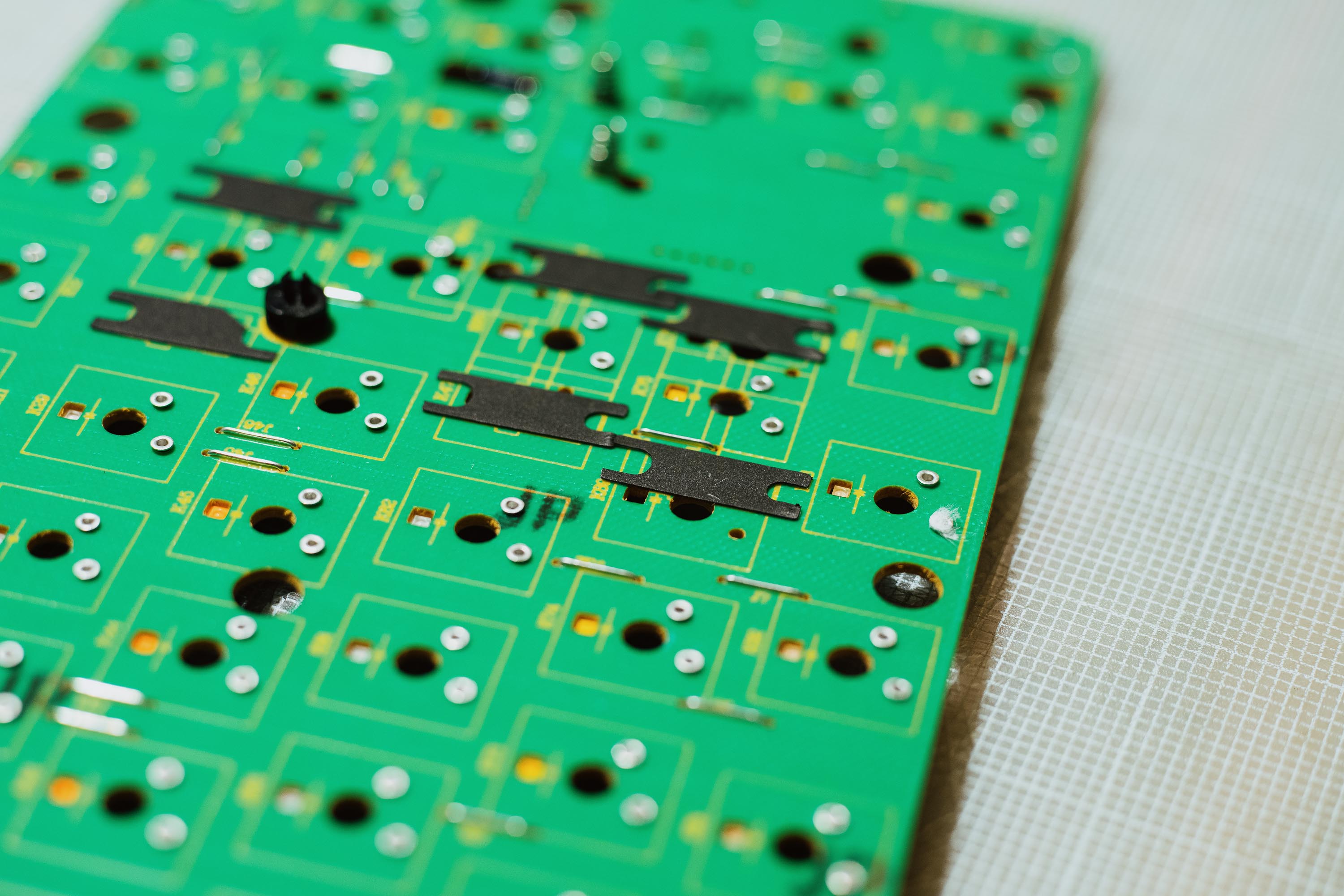
I cleaned the stabilizers and tuned them up using Krytox 205g0 and Permatex grease. I clipped them and placed pads where the stabilizers may hit the PCB.
Here’s the cured silicon mold in the bottom case. I used a similar mold for the Keychron C2 in this post.
Next up is the custom-cut EVA foam. I chose to use a laser engraver for this. However, I traced this out using the switch plate and…that definitely did not include all of the standoffs from the bottom case!
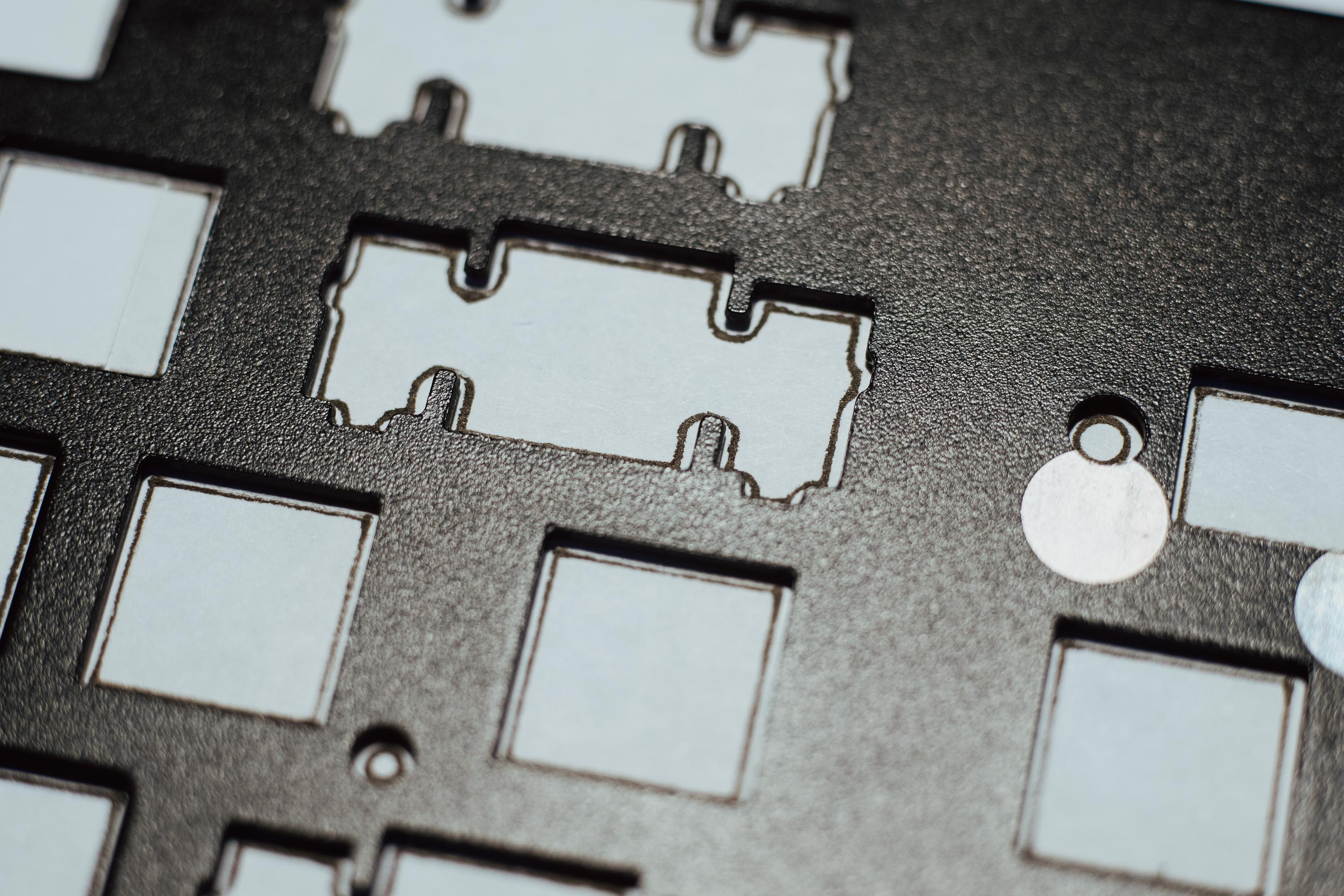
I ended up using a hobby knife to trim the foam in a few places to let the standoffs poke through.
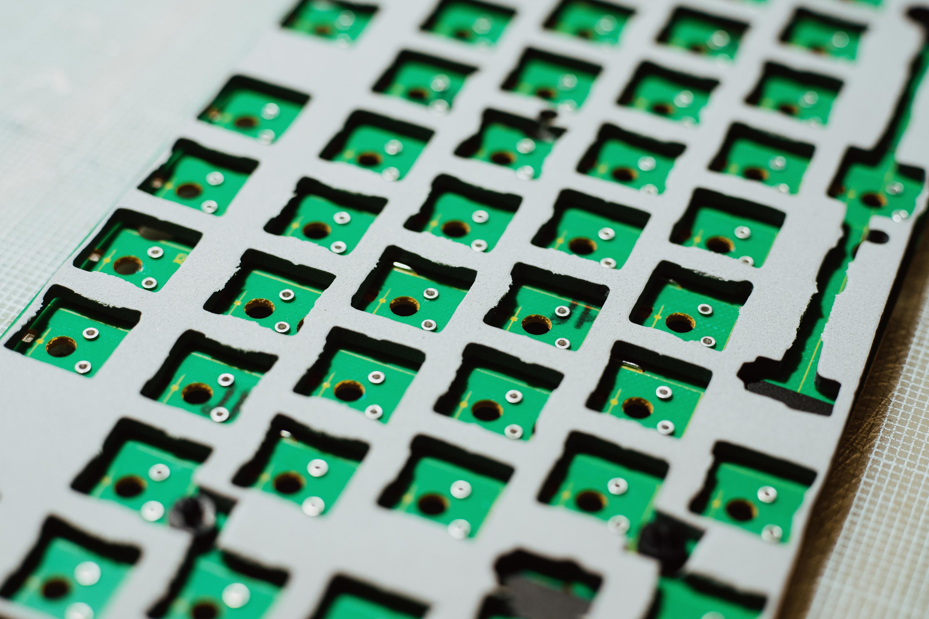
Here’s another photo with the PCB, foam, and bottom case.
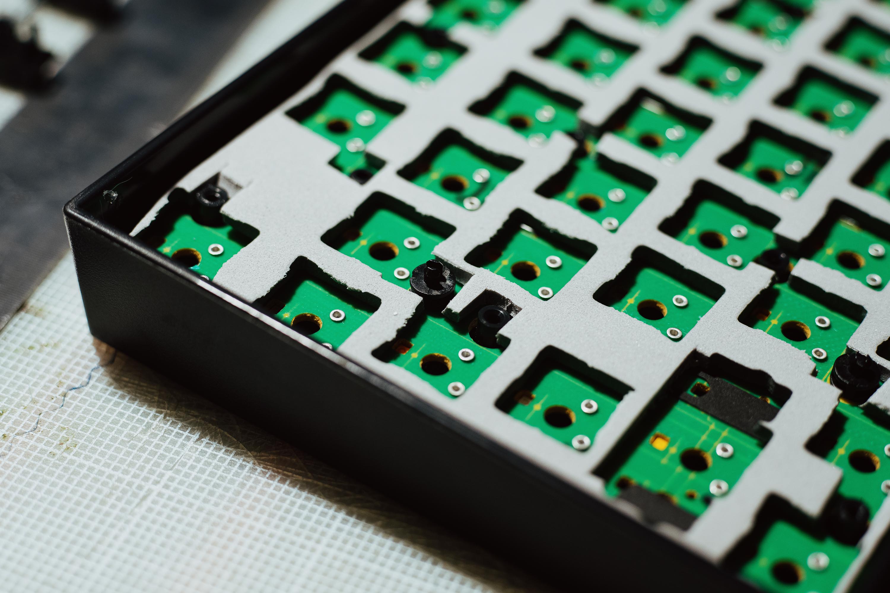
From there, it was a matter of assembly.
Finished board and sound test
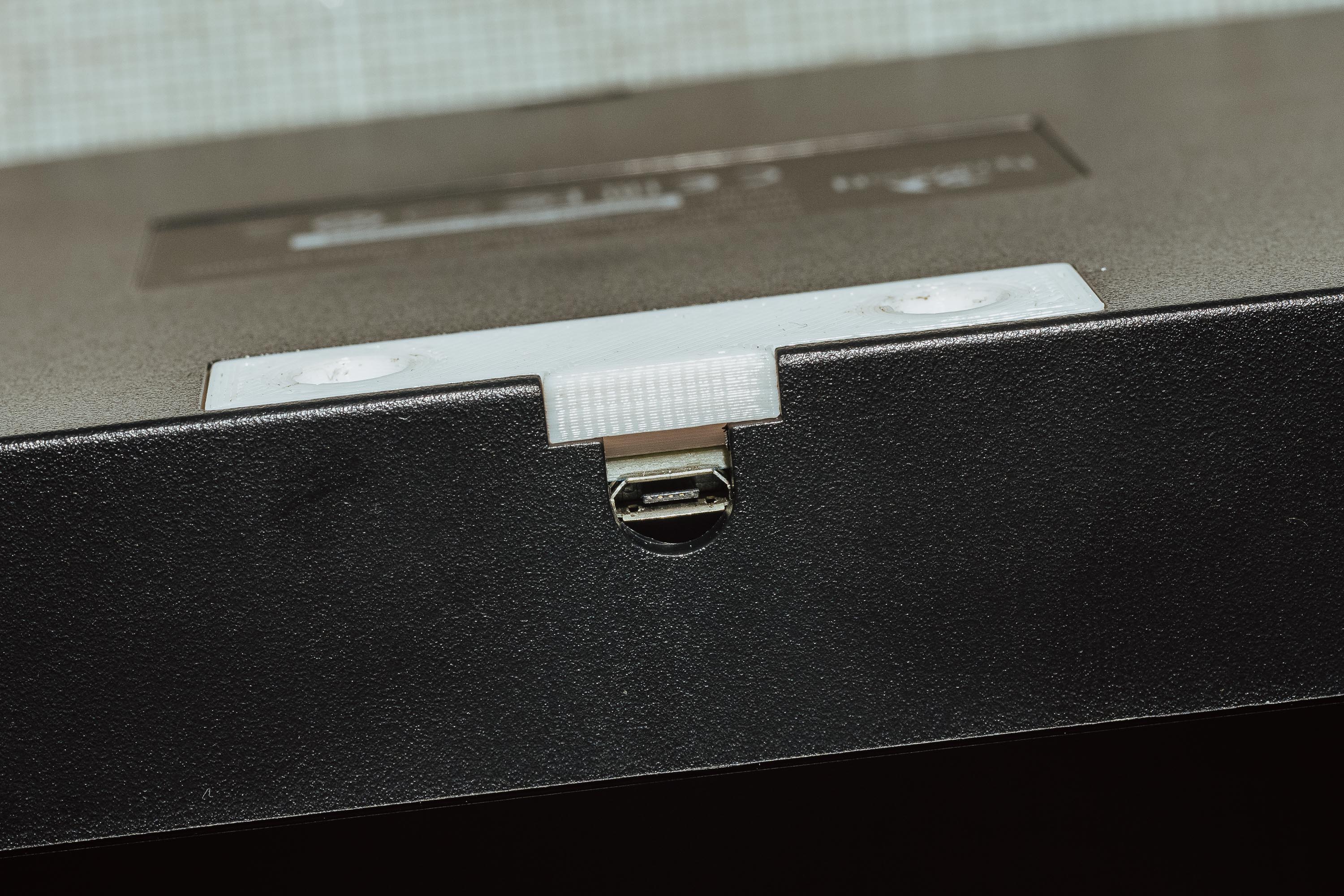
The finished board looks pretty much the same, minus the detachable USB cable. Many folks either erase the Redragon logo using a pencil eraser or 3D print a replacement part.
I chose to use white PETG filament for the part to make the change super visible for this post. I recommend choosing the color that meets your needs, such as black to blend in, or another color to have a bit of pop on the back of the keyboard.
If you didn’t catch it at the beginning of the post, here is the sound test video again.
Thoughts and future modifications
Overall, this was a pretty fun project. It took the mods I’ve done for other keyboards and combined them with some new skills, such as laser-cut foam and custom printed parts. A great learning experience for sure!
Was it worth it? I think so. I think there’s an entire market of folks who are willing to purchase a keyboard around $50-70 provided it gives them a substantially improved experienced compared to a $35 purchase. With these modifications, it provides pretty compelling value.
I chose not to do further modifications like tape, PE foam, completely replaced switches, etc., but a dedicated hobbyist could surely perform these as well for even more improvement, albeit at further time/materials cost.
One area of particular note: the software configurability of the Redragon K552 is pretty lacking compared to other popular keyboards. QMK is one of the most popular open-source firmware for keyboards.
Interestingly, there’s a port of QMK for keyboards like the K552: SonixQMK.
In theory, this brings all of the power of QMK to this keyboard. I haven’t tried it yet, but I plan to do that as a next step.